AI in design engineering
AI2CAD: CAD automation with AI and LLMs
Not a single mouse click in the CAD system.
A large language model (LLM) controls the CAD system. It sets every parameter, builds the geometry and creates the drawing. You provide instructions and approvals through the conversation.
Watch the four steps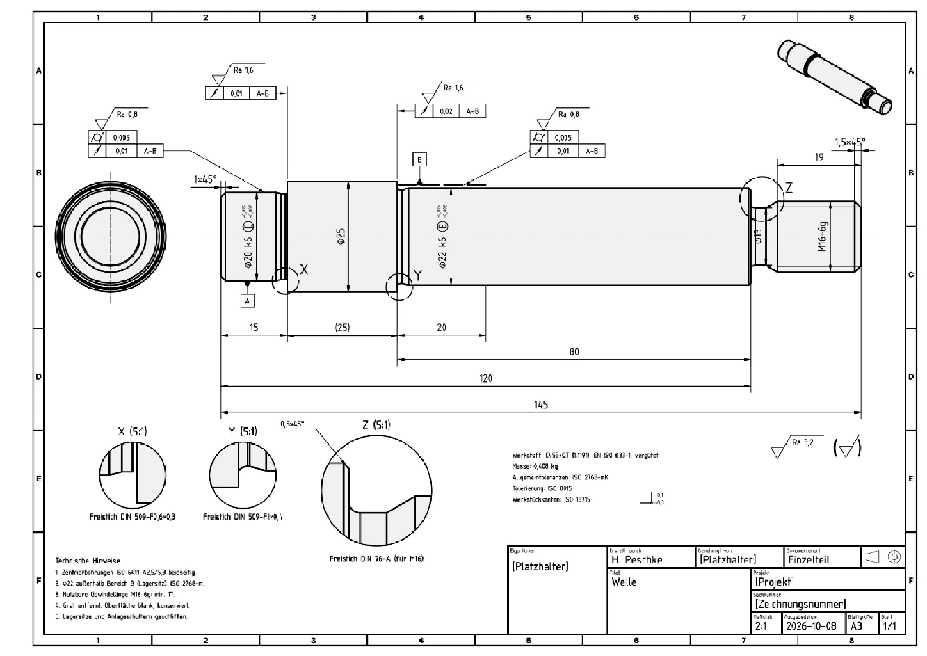
Four chapters. Real model work.
Watch the modelling.
Start with the mounting plate or go straight to the shaft. Chapters 2 to 4 follow a hand sketch through modelling, revision and drawing preparation.
Chapter 01 / 04
From prompt to part
A mounting plate described through dimensions and modelling steps. The language model operates the connected CAD system and builds the geometry step by step. Dimensions remain editable afterwards.
- 180 × 120 × 12 mm base plate built in seven modelling steps
- Holes, counterbores, pockets and corner radii
- Read dimensions and volume back from the resulting geometry
Engineering reviewThe model check compares geometry against the specification. Load capacity and suitability for the intended application require separate assessment.
Open this video on its own pageChapter 02 / 04
From sketch to model
A photograph of a hand sketch becomes the starting point for a stepped shaft. AI separates readable dimensions from derived values and assumptions. Four questions clarify the design before modelling begins.
- Read sketch dimensions and identify missing information
- Document twelve named parameters and their origins
- Test a dimension change: overall length follows the parameter
Engineering reviewMissing dimensions and the simplified thread representation are explicitly agreed. The result is a design model.
Open this video on its own pageChapter 03 / 04
Question the design
AI reads parameters and geometry and flags issues: missing reliefs, sharp shoulders and unresolved functional requirements. Questions, proposed tolerances and approved model changes follow.
- Clarify bearing seats, load case, material and manufacturing
- Explain assumptions and proposed tolerances
- Add reliefs and a lead-in chamfer to the model
Engineering reviewThe demo allows AI to propose assumptions. Bearing selection, standards references and functional dimensions require engineering review.
Open this video on its own pageChapter 04 / 04
From model to drawing
Views, dimensions, tolerance frames and surface specifications take shape on an A3 sheet. AI examines the drawing as an image, corrects overlapping elements and records the remaining review tasks.
- Main views at 2:1, details at 5:1 and an isometric view
- Add fits, datums and technical notes
- Repeat visual checks and propose export for approval
Engineering reviewThe demo leaves a bearing shoulder with insufficient height and individual relief dimensions to check against the standard. Manufacturing approval has not been demonstrated.
Open this video on its own pageOwn development demonstration · German on-screen text · Website editions without audio, product names obscured · Videos load on play
Every parameter. Controlled by the LLM.
The language model operates the CAD system through a tool interface. In the demonstration, it carries out the CAD operations: creating sketches, setting dimensions, building features, selecting views and laying out the drawing. No manual CAD clicks are needed for these steps.
The resulting model remains parametric and editable. Questions and engineering approvals happen in the conversation.
Changed by the LLM, tested and reset to the original value.
Approval needs engineering judgment.
The recordings show an AImation development demonstration. AI proposes dimensions, tolerances and corrections. A design engineer checks function, standards and manufacturability before approving a drawing.
Transfer to your environment depends on the CAD system, available interfaces and your data requirements. The demonstration does not establish compatibility with every CAD system.
Questions about AI in CAD.
What is AI2CAD?
AI2CAD is an AImation demonstration of CAD automation using a large language model (LLM). The LLM operates a connected CAD system, creates parametric parts, proposes design corrections and prepares a technical drawing. Four videos show a mounting plate and a stepped shaft.
Can a language model operate CAD without mouse clicks?
In this demonstration, the language model performs the CAD operations through a tool interface. It sets parameters, creates sketches and features, selects views and prepares the drawing. Instructions, questions and approvals are exchanged in conversation. No manual mouse clicks in the CAD system are used for these steps.
Can AI turn a hand sketch into an editable CAD model?
Chapter 2 shows a photographed hand sketch becoming a parametric shaft with twelve named parameters. The model separates readable dimensions, derived values and assumptions. Missing information is clarified before modelling. A parameter change from 25 to 30 mm changes overall length from 145 to 150 mm.
Who is this CAD automation demonstration for?
AI2CAD addresses design engineers, product developers and heads of engineering in technical SMEs. Recurring modelling tasks, dimension variants and drawing preparation are possible starting points. The CAD interface, design rules and required review steps must be assessed for each company.
Does AI2CAD work with our CAD system?
The videos demonstrate one connected CAD system. Transfer depends on the available API or automation interface, permitted tools and data requirements. In an initial conversation, AImation checks your CAD environment and a specific design task. Compatibility with every CAD system is not established.
Is the AI-generated drawing ready for manufacturing?
The demonstrated drawing still requires engineering review. Chapter 4 identifies a bearing shoulder with insufficient height and relief dimensions that need checking against the relevant standard. A design engineer must approve function, fits, standards and manufacturability before the drawing goes to a supplier.
Bring your part.
A recurring part, a typical sketch, a drawing task. In an initial conversation, we will discuss which step is worth testing in your environment.